
Parameters / Specifications
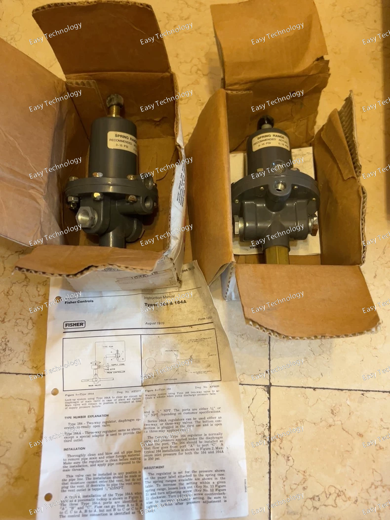
Model: 164A/18
Type: Three‑way pneumatic switching valve
End connections: ¼ inch NPT (for typical 164A series)
Maximum inlet pressure: 250 psig (≈17.2 bar)
Outlet/actuation (switch) pressure range: ~0‑35 psig (≈0‑2.4 bar) (common for the “/18” suffix in listings)
Ports: Three ports (A, B, C) for switching or venting operations
Construction: Rugged compact body designed for pneumatic signal switching
Media: Instrument air or compatible control gas
Typical applications: Diverting or venting control signal flow in pneumatic systems, actuator vent/close signal switching
Weight: Approximately 4 lbs (≈1.8 kg) for typical body (based on similar model data)
Specifications / Parameters
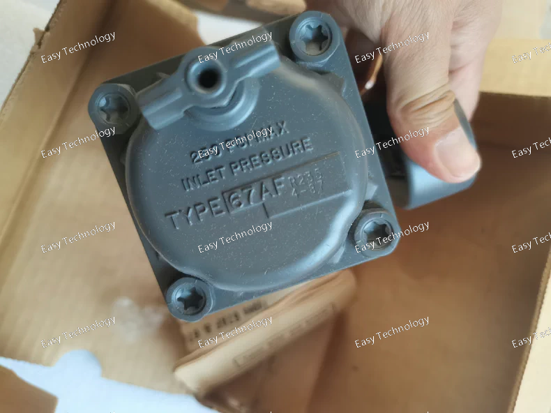
Model: 67AF
Type: Pressure regulator with integral filter (filtered regulator)
Series: Fisher “67” family (instrument/regulator class)
Typical maximum inlet (body) pressure: 250 psig (≈17.2 bar) for standard filtered versions in this family
Connections: ¼ inch NPT for the small instrument/regulator size version
Outlet (regulated) pressure range: Example‑listed units show spring ranges such as 0‑35 psig (≈0‑2.4 bar)
Built‑in filter: Yes (to remove particulates upstream of the regulator internals)
Temperature limits (depending on elastomer/filter materials):
With standard elastomer (nitrile): approx –40 °F to +180 °F (≈ –40 °C to +82 °C)
With fluorocarbon elastomer (FKM): approx 0 °F to +300 °F (≈ –18 °C to +149 °C)
With silicone/low‑temperature bolting option: approx –60 °F to +180 °F (≈ –51 °C to +82 °C)
Approximate weight: For the small instrument version, approx 1 lb (≈0.5 kg)
Typical application: Clean, regulated instrument air/gas supply for pneumatic actuators, controllers, measurement instrumentation.
Technical Specifications
Category Specification
Model Type 1301F-1
Type Self-Operated Pressure Reducing Regulator
Function To reduce a higher, variable inlet pressure to a stable, lower outlet pressure.
Power Source Self-Operated (Uses energy from the process fluid)
Body Style Globe Valve Body
End Connections Flanged (typical for "F" designation, e.g., ANSI Class 125 or 150).
Orifice Size Defined by the "-1" code, which corresponds to a specific diameter.
Outlet Pressure Range Defined by the "F-1" configuration. This is a field-adjustable range, but the spring is selected for a specific span. Example ranges could be 5-20 psig or 10-50 psig. The exact range must be confirmed from factory data sheets.
Maximum Inlet Pressure Typically up to 400 psig (28 bar) for standard bodies.
Flow Coefficient (Cv) Determined by the "-1" orifice size. This value is critical for sizing the valve for the application's flow rate.
Temperature Range Standard with Buna-N diaphragm: -20°F to +180°F (-29°C to +82°C).
Materials of Construction Body: Cast Iron (standard), Ductile Iron, Brass.
Trim (Plug/Seat): Stainless Steel (standard).
Diaphragm: Buna-N (standard).
Technical Specifications
Category Specification
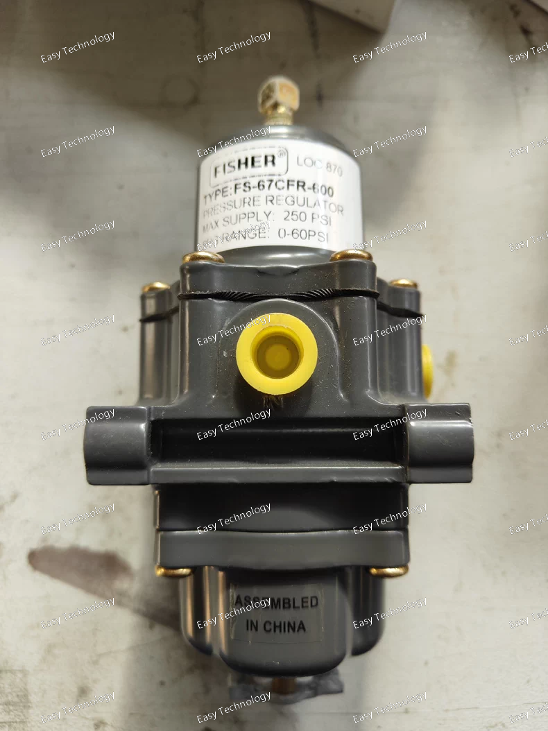
Fisher Part Number FS-67CFR-600
Description Filter Regulator Mounting Kit
Compatible Component Fisher 67CFR Series Actuator Pilots or related pneumatic systems
Function Provides the physical interface to mount a filter regulator to the target component.
Kit Contents Typically includes mounting bracket, bolts, gaskets, fittings, and other necessary hardware.
Materials Components are typically made from plated carbon steel and stainless steel for corrosion resistance.
Parameters / Specifications
Model: FS‑67CFR‑224
Series: 67C Series Instrument Supply Regulators
Type: Direct‑operated regulator with integral filter and internal relief valve
Body Material: Aluminum alloy
End Connections: ¼ inch NPT inlet and outlet
Maximum Inlet Pressure: 250 psig (≈ 17.2 bar)
Outlet (Regulated) Pressure Range: 0‑35 psig (≈ 0‑2.4 bar)
Maximum Emergency Outlet Pressure: 50 psig (≈ 3.4 bar) above setpoint
Filter: Integral, for particulate removal
Internal Relief Valve: Yes, for downstream protection
Temperature Capability:
Nitrile (NBR): –40 °F to +180 °F (≈ –40 °C to +82 °C)
Fluoroelastomer (FKM): 0 °F to +300 °F (≈ –18 °C to +149 °C)
Silicone (VMQ): –60 °F to +180 °F (≈ –51 °C to +82 °C)
Approximate Weight: ~0.5 kg
Media / Application: Clean air or compatible gases for instrumentation or pneumatic systems
Features:
Compact and lightweight construction
Panel or inline mounting
Replaceable filter element
Soft‑seat relief valve prevents over‑pressure and leakage
Durable construction suitable for long-term instrumentation service
Specifications / Parameters
Model: HSR‑CHGBLYN
Regulator type: Pressure reducing regulator, direct‑acting, with internal relief
Body material: Cast iron
End connections: 1″ NPT inlet/outlet (globe body style)
Maximum operating inlet pressure: 125 psig (≈8.6 bar)
Maximum emergency inlet pressure: 150 psig (≈10.3 bar)
Outlet (regulated) pressure range: 12.5 to 20 inches w.c. (approx. 31 to 50 mbar) for one spring range; other available spring ranges include 4‑6” w.c., 6‑8” w.c., 8‑10” w.c., 10‑12.5” w.c., 12.5‑20” w.c., 20‑35” w.c., and 1.25‑2.2 psig (0.09‑0.15 bar)
Maximum allowable outlet pressure differential (to avoid internal part damage): approx. 3 psig (≈0.21 bar) above setpoint
Temperature capability: approx. –20 °F to +160 °F (≈ –29 °C to +71 °C)
Orifice size / capacity guidelines: for orifice sizes from 1/8″ to 1/2″, the maximum operating inlet pressures vary (for example for a 1/8″ orifice: 125 psig / 8.6 bar; for a 1/2″ orifice: ~20 psig / 1.4 bar)
Typical weight: ~4 lb (≈2 kg)
Application: Fuel‑gas supply regulation in residential, multi‑dwelling, commercial or light industrial installations, meeting or exceeding ANSI B109.4 / CGA 6.18 standards.
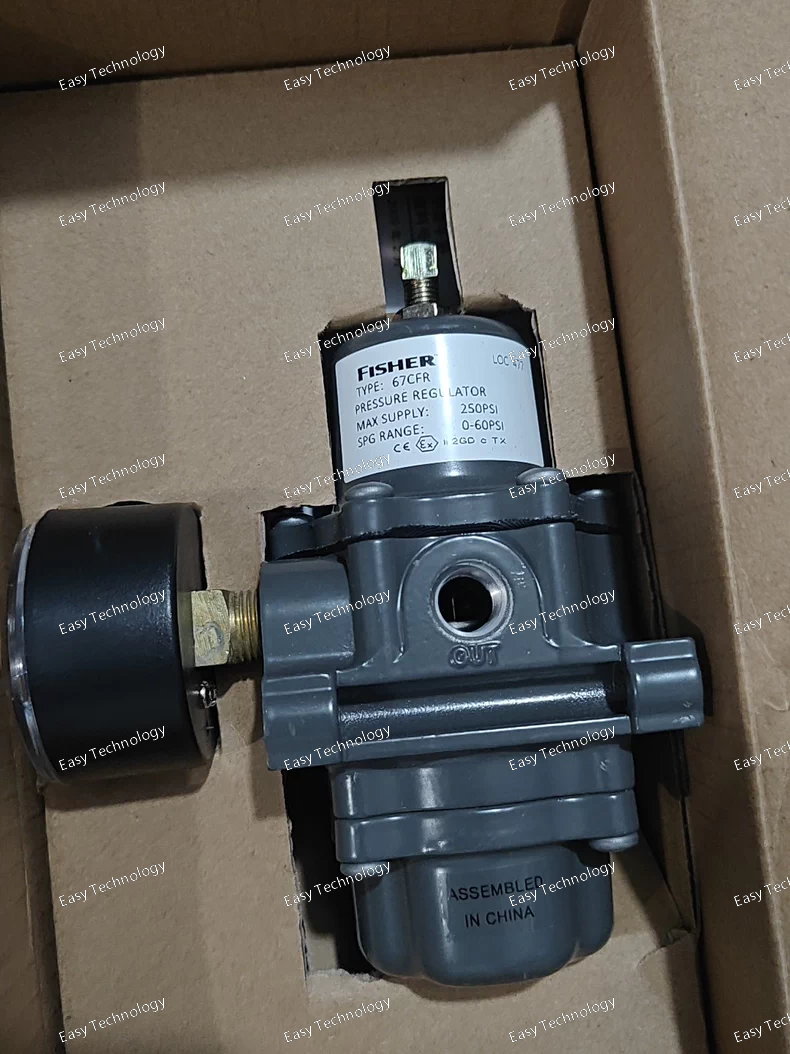
Parameters / Specifications
Model: Fisher 67CFR‑225 (and implied option suffix “/C4”)
Series: Fisher 67C Series Instrument Supply Regulators
Construction / Type: Filtered regulator with internal relief (integral filter + internal relief)
Body Material: Aluminum alloy (standard for 67C/67CF/67CFR)
Connections / Body Size: ¼ inch NPT (inlet and outlet)
Maximum Inlet Pressure (Body Rating): 250 psig (≈ 17.2 bar)
Outlet (Regulated) Pressure Range (spring range for “‑225”): 0–60 psig (≈ 0–4.1 bar)
Maximum Emergency Outlet Pressure (i.e., the built‑in relief will relieve when outlet exceeds setpoint by this margin): 50 psig (≈3.4 bar) above outlet setting
Filter: Integral 5‑micron polyethylene (standard) filter included
Temperature Capability (depending on elastomer / filter material):
NBR (nitrile) elastomers: approx –40 °F to +180 °F (≈ –40 °C to +82 °C)
FKM (fluoroelastomer) elastomers: approx 0 °F to +300 °F (≈ –18 °C to +149 °C)
VMQ (silicone) diaphragm with low‑temperature bolting: approx –60 °F to +180 °F (≈ –51 °C to +82 °C)
Approximate Weight: ~1 lb (≈0.5 kg)
Media / Typical Use: Air or compatible clean gases, for pneumatic instrumentation, controllers, panel‑mounted systems, regulators supplying instrument air.
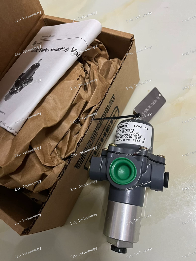
Parameters / Specifications
Model: Fisher 167DA‑11
Series: Fisher 167D Series Switching Valves
Type: Three‑way switching valve (Ports A and C are main flow paths; Port B and control/vent Port D as described)
Body Size / End Connections: Ports A and C: ¼ in or ½ in NPT; Ports B and D: ¼ in NPT
Maximum Inlet (Body) Pressure: 125 psig (≈ 8.6 bar) for standard 167DA configurations
Set Pressure (Control Spring Range): One of the available spring ranges for 167DA series (for example 14‑20 psig, 16‑35 psig, 25‑60 psig, 40‑125 psig) — the “‑11” suffix corresponds to one of these, detailed value should be checked in the ordering code
Temperature Capability (Standard Service): ‑20 °F to +180 °F (≈ ‑29 °C to +82 °C) for standard construction; low‑temperature service or high‑temperature service versions available
Approximate Weight: ~1.2 lb (≈0.5 kg)
Flow / Sizing Coefficient (Wide‑Open): For ¼ in NPT version: Cv ≈ 30.58; for ½ in NPT version: Cv ≈ 32.22
Application: Switching pneumatic control signals, instrument air systems, diverting flow in control circuits, actuation logic for pneumatic systems
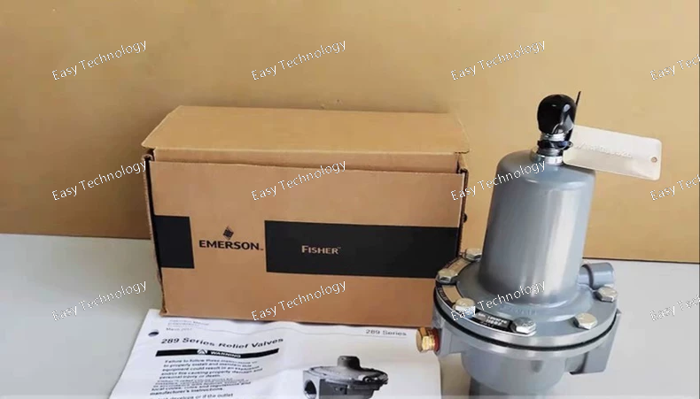
Parameters / Specifications
Model: Fisher 289H‑41
Series: Fisher 289 Series Relief / Back‑Pressure Regulators
Body Size / End Connections: 1″ NPT (inlet & outlet) for the “H” size version
Relief (Set) Spring Range: Approx 1.0 to 4.5 psig (≈0.07 to 0.31 bar) for the “‑41” variant
Maximum Allowable Inlet Pressure (Body Rating): Approx 100 psig (≈6.9 bar) for this body size
Temperature Capability (depending on elastomer):
Nitrile (NBR) / Neoprene (CR): –20 °F to +150 °F (≈ –29 °C to +66 °C)
Fluoroelastomer (FKM): 20 °F to +300 °F (≈ –7 °C to +149 °C) (available on “H/HH” types)
Approximate Weight: ~4 lb (≈2.0 kg) for the 1″‑NPT size “H” body
Media / Application: Non‑corrosive gas or air service, used as a relief device or back‑pressure regulator in downstream systems to limit pressure, reduce pressure surges, protect equipment
Features:
Spring‑loaded throttling action with minimal pressure surge during relief
Compact design for installation where space may be limited
Reliable, relatively simple construction for high dependability
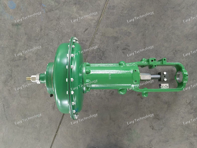
Parameters / Specifications
Model: 667‑46i
Actuator Type: Spring‑opposed diaphragm actuator, reverse‑acting
Series: Fisher Type 667
Size: 46i diaphragm class
Travel (Maximum Stroke): Up to 76 mm (~3.0 in) standard; up to 102 mm (~4.0 in) for extended stroke versions
Signal Pressure Range: Typical 3‑15 psig (0.2‑1.0 bar) or 6‑30 psig (0.4‑2.0 bar)
Operating Temperature Range: Standard –58 °F to +180 °F (–50 °C to +82 °C) depending on diaphragm material and configuration
Construction Materials: Cast iron/steel body, molded diaphragm, heavy‑duty spring case
Features:
Integral mounting pad for digital valve positioners
High thrust capability, linear response
Optional manual handwheel, travel stops, and low-temperature variants
Typical Applications: Sliding‑stem control valves, industrial process control requiring failsafe action and precision response
Fail State: Spring drives actuator to fail position (commonly closed) on loss of supply signal
Approximate Weight: Varies with size and accessories; typically tens of pounds (kilograms)