Key Parameters
Item Specification / Description
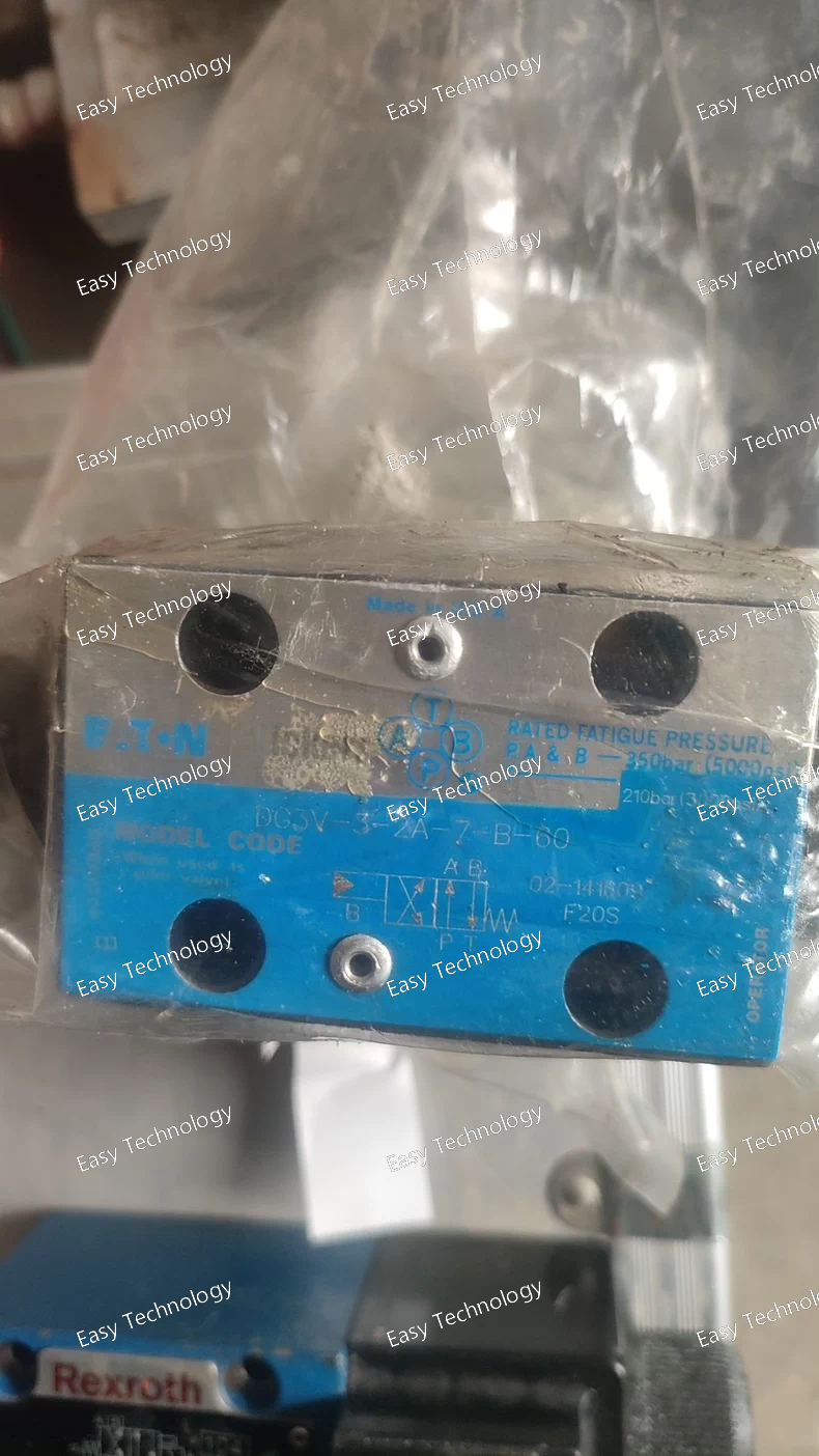
Valve Type Directional control valve (hydraulically operated)
Series / Size Interface DG3V-3, ISO 4401‑03 / CETOP 3 / NFPA D03 (NG6 / D03)
Spool / Center / Return Spool type “2A”; spring‑offset end-to-end (spring return) configuration (center return when pilot removed)
Maximum Operating Pressure (P, A, B ports) 350 bar (≈ 5000 psi)
Tank Port (T) Rating 210 bar (≈ 3000 psi)
Maximum Flow Rate Up to 38 L/min (≈ 10 US gpm) under nominal conditions
Fluid / Oil Compatibility Petroleum‑based hydraulic oils
Recommended Fluid Cleanliness 19/17/14 µm (or better)
Seal Material Buna‑N (standard)
Mounting / Installation Subplate / manifold mounted
Temperature Range (ambient / fluid) –20 °C to +70 °C (–4 °F to +158 °F)
Valve Stage Single‑stage hydraulic actuation
Port / Interface Type ISO 4401‑03 subplate interface (standard bolt‑on)
Parameter Description / Value Notes
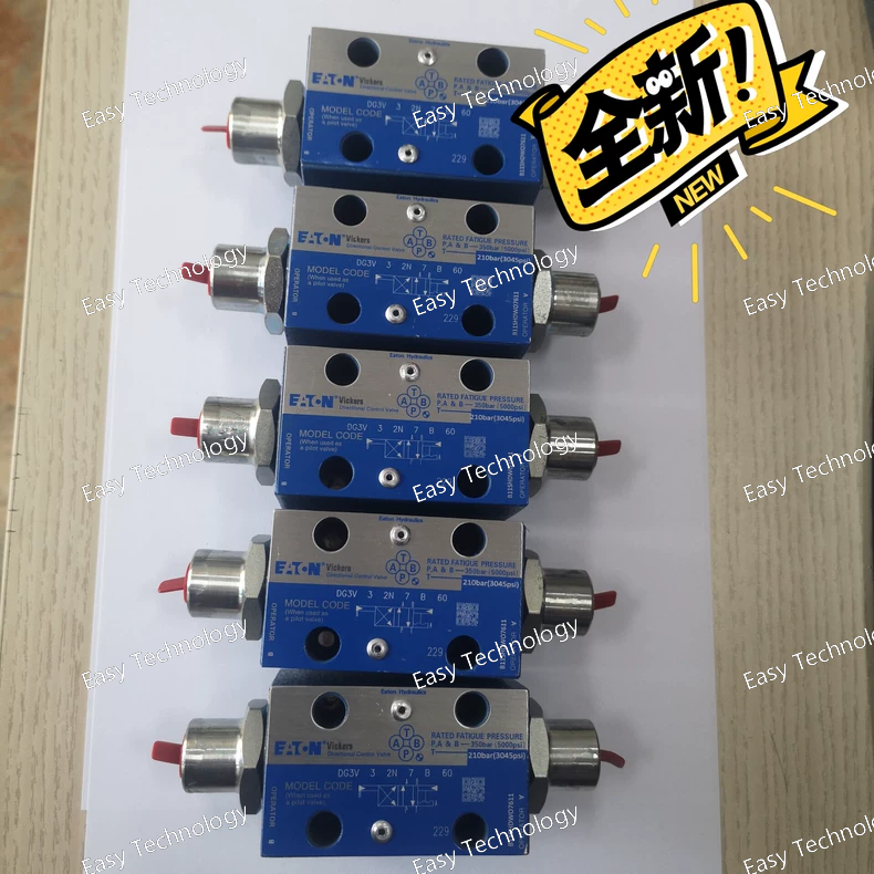
Product Line Eaton DG3V First Generation Directional Valve
Porting Size 3 (NG03 / CETOP 3 / NFPA D01) Standard subplate interface
Spool Type 2N A "B" type spool with negative overlap (underlap). This provides a small fixed pilot flow at center for stability and is common for industrial applications.
Actuator Type 7B Single Solenoid with Spring Centered/Return and Mechanical Detent.
• Position 1: Solenoid energized (spring return when de-energized).
• Position 2: Spring-centered neutral.
• Position 3: Mechanical detent (latched position, requires opposite solenoid signal to release).
Maximum Operating Pressure 350 bar (5,075 psi)
Maximum Flow Rate Approx. 19 L/min (5 US gpm) Dependent on spool and pressure drop.
Voltage Not specified in base model Requires a separate solenoid coil (e.g., 24 VDC, 110 VAC) specified by a part number like 6034967-001.
Solenoid Connector Not specified in base model Typically a DIN 43650 Form A connector when a coil is attached.
Center Position Determined by Spool (e.g., 2N) The "2N" spool typically has a specific center configuration (often "Y" type, allowing the actuator to float).
Weight Approx. 2.5 kg (5.5 lbs)
Parameter Description / Value Notes
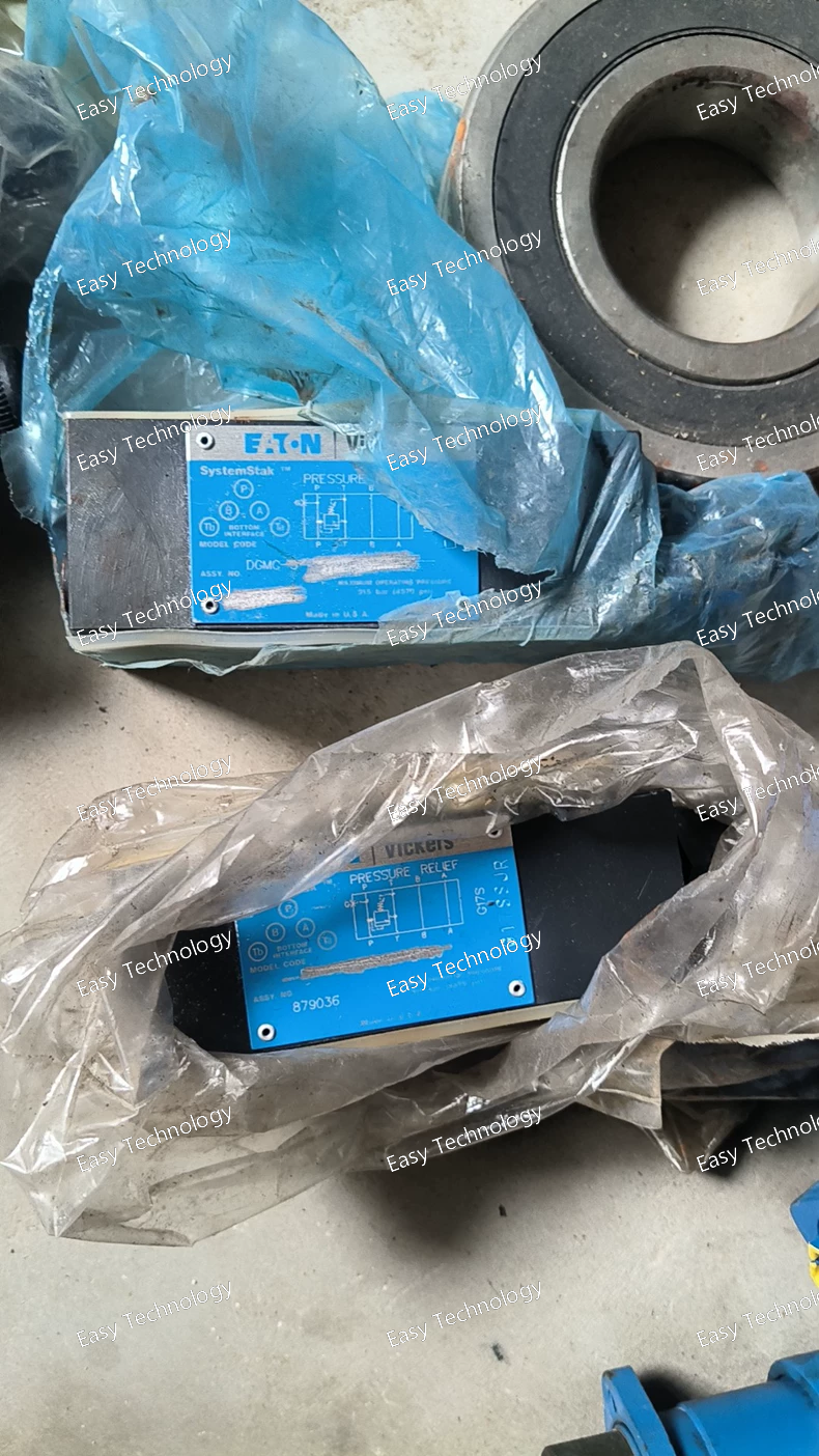
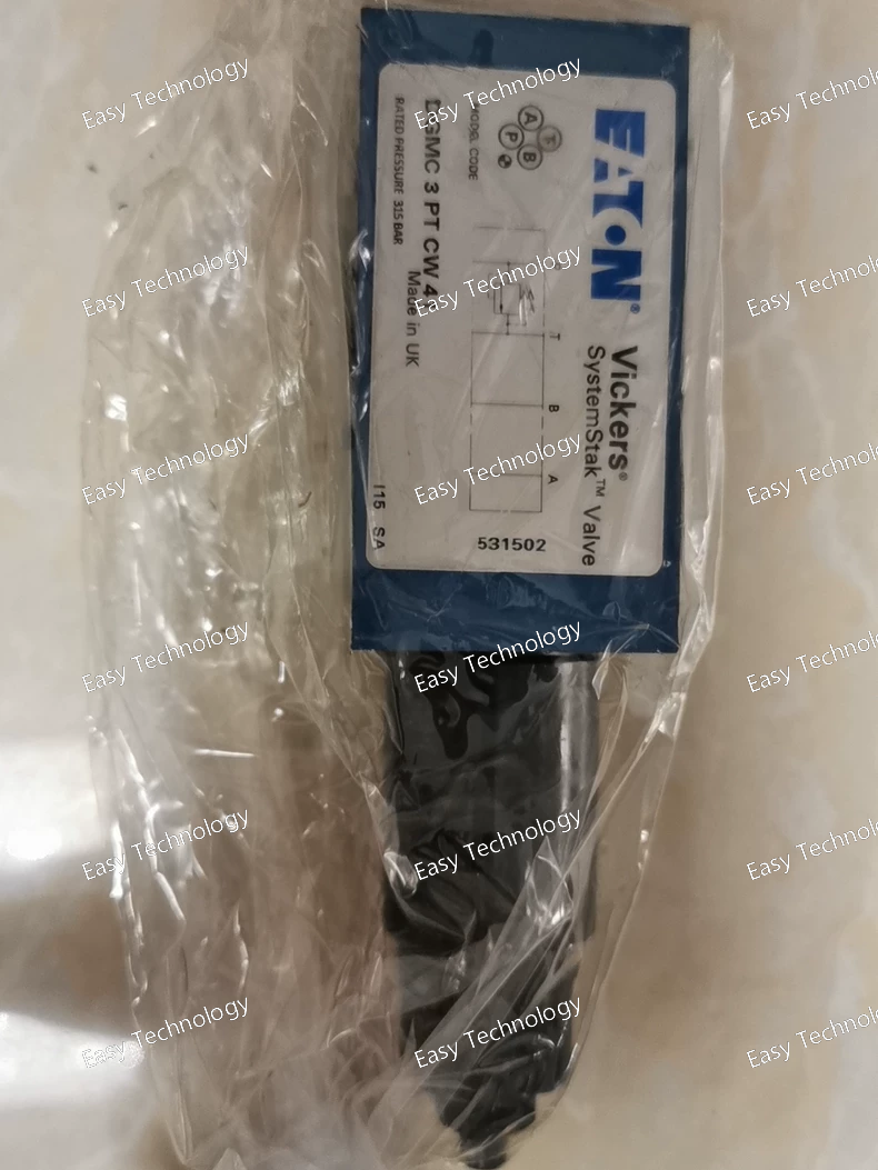
Product Line Eaton DGMC Directional Control Valve Motor Control Sections
Porting Size 5 (NG05 / CETOP 5 / NFPA D02) Matches the size of the directional valve it is stacked with (e.g., DG4V-5).
Relief Valve Type PT (Adjustable Cross-Line Relief) P for adjustable relief, T for the specific pressure range and design.
Neutral Bypass Type GH A specific configuration for neutral bypass (freewheeling) and internal flow paths.
Design Variant B-30 Specific design version, manufacturing, or adjustment range code.
General Performance Data
Maximum Operating Pressure 350 bar (5,075 psi)
Adjustable Relief Pressure Range e.g., 40 - 250 bar (580 - 3625 psi) *This is a critical detail that must be confirmed from the technical datasheet for the exact -B-30 suffix.*
Relief Valve Capacity Full pump flow
Bypass Flow Capacity Full pump flow
Mounting "Sandwiched" between directional valve and subplate
Parameter Description / Value Notes
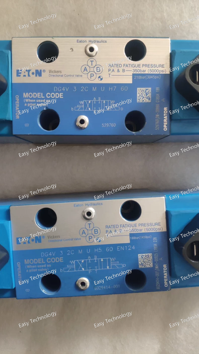
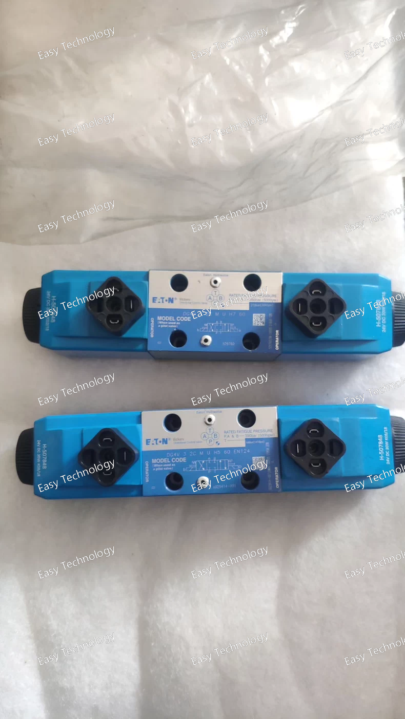
Product Line Eaton DG4V Second Generation
Type Proportional Directional Control Valve 4-way, 3-position
Porting Size NG03 (CETOP 3 / NFPA D01) Standard subplate interface
Maximum Operating Pressure 350 bar (5,075 psi)
Maximum Flow Rate Approx. 19 L/min (5 US gpm) *Dependent on spool and pressure drop (e.g., Δp = 10 bar).*
Spool Type 2C (B-spool with critical center overlap) Industrial spool for precise actuator control.
Center Position M (Closed Center / All Ports Blocked) In the center (neutral) position, all work ports (A, B) and the pressure port (P) are blocked, and the tank port (T) is open. This holds an actuator in place.
Solenoid Type Proportional Solenoid Wet armature design
Feedback Type Integrated LVDT The spool has a built-in LVDT for closed-loop position control.
Electrical Connector U (DIN 43650 Form A, 4-pin) Standard industrial connector for valve power and feedback.
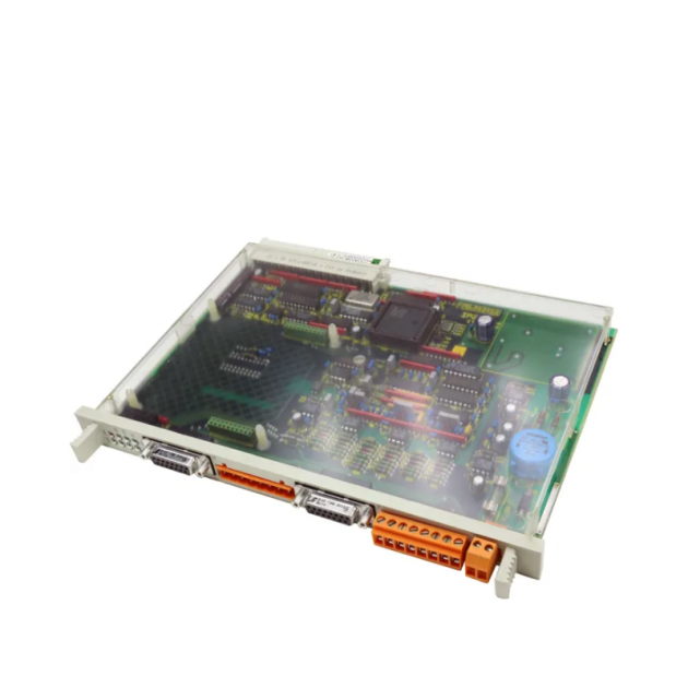
Electronics Type H5 External amplifier required. The valve itself has no onboard control electronics.
External Amplifier Input Signal Typically ±10 VDC or 4-20 mA Defined by the external amplifier model used (e.g., EEM-XXX-XXX).
External Amplifier Supply Voltage Typically 24 VDC Defined by the external amplifier model.
EN124 European Norm 124 This indicates the valve conforms to specific European standards, likely related to its solenoid connector, which is a EN 175301-803 Form C (3-pin) connector, commonly used in mobile equipment.
Parameter Description / Value Notes
Product Line Eaton DG4V Second Generation
Type Proportional Directional Control Valve 4-way, 3-position
Porting Size NG03 (CETOP 3 / NFPA D01) Standard subplate interface
Maximum Operating Pressure 350 bar (5,075 psi)
Maximum Flow Rate Approx. 19 L/min (5 US gpm) *Dependent on spool and pressure drop (e.g., Δp = 10 bar).*
Spool Type 2C (B-spool with critical center overlap) Provides a good compromise between low leakage and control resolution.
Center Position M (Closed Center / All Ports Blocked) In the center (neutral) position, all work ports (A, B) and the pressure port (P) are blocked, and the tank port (T) is open. This holds an actuator in place.
Solenoid Type Proportional Solenoid Wet armature design
Electrical Connector U (DIN 43650 Form A, 4-pin) Standard industrial connector
Integrated Electronics H7 On-board amplifier card for open-loop control
Input Signal ±10 VDC or 4-20 mA Selectable via internal dip-switches
Supply Voltage (to amplifier) 12-30 VDC For the H7 amplifier
Coil Voltage Derived from internal amplifier Typically 12-24 VDC pulsed
Hysteresis < 3% Typical for open-loop proportional valves
Repeatability < 2% Typical for open-loop proportional valves
IP Rating IP65 (with connector properly installed) Dust-tight and protected against water jets
Hydraulic Fluid Mineral-based hydraulic oil to ISO 11158
Fluid Viscosity Range 10 to 400 cSt (50 to 2000 SUS)
Operating Temperature Range -20°C to +70°C (-4°F to +158°F)
Parameter Description / Value Notes
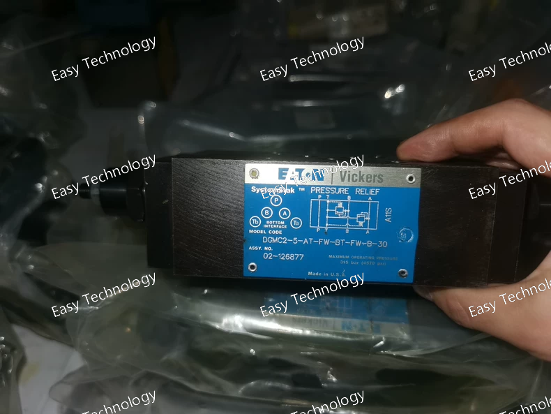
Product Line Eaton DGMC2 Dual Motor Control Section Series
Porting Size 5 (NG05 / CETOP 5 / NFPA D02) Matches the size of the directional valve it is stacked with.
Circuit 1 Relief Valve AT (35 bar / 500 psi) Fixed setting cross-line relief for Motor 1.
Circuit 1 Bypass Type FW (Freewheel Bypass) Allows Motor 1 to freewheel in neutral.
Circuit 2 Relief Valve BT This is a specific fixed pressure setting, different from "AT". The exact pressure value must be confirmed from the datasheet (e.g., it could be 100 bar, 150 bar, etc.).
Circuit 2 Bypass Type FW (Freewheel Bypass) Allows Motor 2 to freewheel in neutral.
Design Variant B-30 Specific design version or manufacturing code.
General Performance Data
Maximum Operating Pressure 350 bar (5,075 psi)
Relief Valve Capacity Full pump flow for each circuit
Bypass Flow Capacity Full pump flow for each circuit
Mounting "Sandwiched" between a dual directional valve and subplate
Parameter Description / Value Notes
Product Line Eaton DG4V Second Generation
Type Proportional Directional Control Valve 4-way, 3-position
Porting Size NG03 (CETOP 3 / NFPA D01) Standard subplate interface
Maximum Operating Pressure 350 bar (5,075 psi)
Maximum Flow Rate Approx. 19 L/min (5 US gpm) *Dependent on spool and pressure drop (e.g., Δp = 10 bar).*
Spool Type 0B (O-spool with critical center overlap) Provides a blocked center with minimal leakage, excellent for load holding.
Center Position M (Closed Center / All Ports Blocked) In the center (neutral) position, all work ports (A, B) and the pressure port (P) are blocked, and the tank port (T) is open. This holds an actuator in place.
Solenoid Type Proportional Solenoid Wet armature design
Electrical Connector U (DIN 43650 Form A, 4-pin) Standard industrial connector
Integrated Electronics H7 On-board amplifier card for open-loop control
Input Signal ±10 VDC or 4-20 mA Selectable via internal dip-switches
Supply Voltage (to amplifier) 12-30 VDC For the H7 amplifier
Coil Voltage Derived from internal amplifier Typically 12-24 VDC pulsed
Hysteresis < 3% Typical for open-loop proportional valves
IP Rating IP65 (with connector properly installed) Dust-tight and protected against water jets
Hydraulic Fluid Mineral-based hydraulic oil to ISO 11158
Fluid Viscosity Range 10 to 400 cSt (50 to 2000 SUS)
Operating Temperature Range -20°C to +70°C (-4°F to +158°F)
Parameter Description / Value Notes
Product Line Eaton DGMC Directional Control Valve Motor Control Sections
Porting Size 3 (NG03 / CETOP 3 / NFPA D01) Matches the size of the directional valve it is stacked with.
Relief Valve Type PT (Adjustable Cross-Line Relief) P for adjustable relief, T for the specific pressure range and design.
Neutral Bypass Type CW Standard neutral bypass configuration for freewheeling.
Design Variant 41 Specific design version or manufacturing code.
General Performance Data
Maximum Operating Pressure 350 bar (5,075 psi)
Adjustable Relief Pressure Range e.g., 40 - 250 bar (580 - 3625 psi) *The exact adjustable range must be confirmed from the technical datasheet for the exact -41 variant.*
Relief Valve Capacity Full pump flow
Bypass Flow Capacity Full pump flow
Mounting "Sandwiched" between directional valve and subplate
Parameter Description / Value Notes
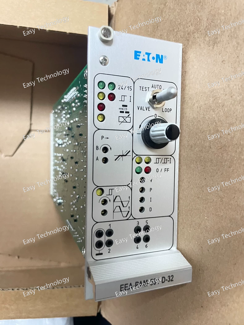
Product Line Eaton EEA-PAM Pro-FX Amplifier Module Series
Model / Function 581 Specific model within the Pro-FX series, defining its core functionality and I/O.
Command Input Type D This letter typically defines the standard input type. "D" often denotes a default or standard analog input configuration (e.g., ±10 VDC). The exact meaning should be verified in the manual.
Option Code 32 This suffix defines specific factory options, such as the type of fieldbus communication (e.g., CANopen, J1939, PROFIBUS-DP) or other special features. "32" often indicates a specific fieldbus protocol.
General Performance Data
Supply Voltage Typically 24 VDC (10 - 30 VDC range) Standard for industrial controls.
Output Current Typically up to 3.0 A (PWM) Sufficient to drive most proportional solenoid coils.
Command Inputs Typically ±10 VDC, 0-20 mA, 4-20 mA Selectable via software.
Communication Interface Defined by -32 suffix (e.g., CANopen) Allows for parameter setting, diagnostics, and closed-loop control via a network.
IP Rating IP20 (for cabinet mounting) Designed to be installed inside a protective control cabinet.
Ambient Temperature Range 0°C to +55°C (+32°F to +131°F) Standard industrial temperature range.
Mounting DIN rail mount (35mm)
Key Parameters
Item Specification / Description
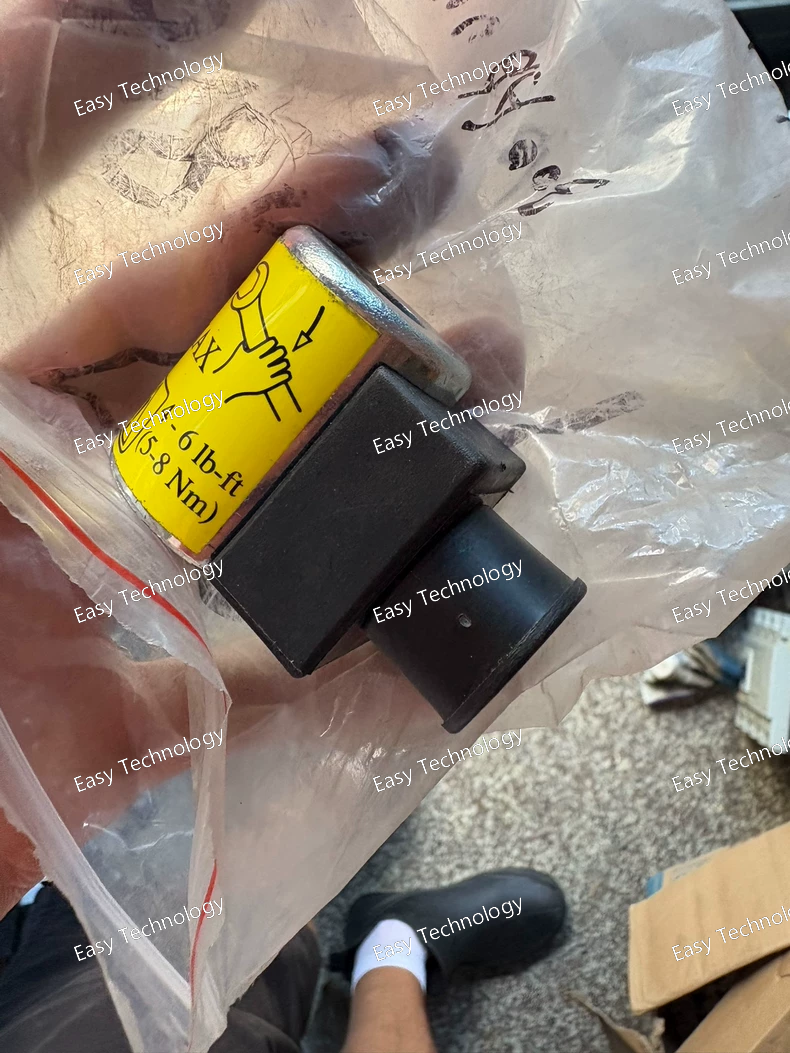
Product Type Solenoid coil for hydraulic valve
Model / Part Number 300AA00006A
Coil Series / Size Rating “Size 8 and 210 bar” coil series
Voltage Rating 230 V AC (with full‑bridge rectifier, AC coil) — other voltage variants may exist depending on variant
Connector / Interface DIN 43650-A (ISO 4400) connector
Duty / Protection Duty rating 85%–110% voltage range; environmental protection ~ IP65 (glass‑filled nylon encapsulation)
Application For harvesters, refuse haulers, mobile & industrial hydraulic systems
Controlled Valve Pressure Rating (when used with valve) Up to ~210 bar (depending on valve)
Typical Installation Screw‑in cartridge or subplate‑mount valve bodies supporting compatible coil size
Operating Temperature (fluid/environment) Suitable for typical hydraulic fluid use; coil material and insulation designed for industrial hydraulic environments
Fluid Compatibility (when mounted on valve) Common hydraulic fluids: e.g. MIL‑H‑5606, SAE 10, SAE 20, etc.
Coil Dimensions / Weight Approx. coil height ~ 2.25″, weight light (~0.14 kg / 0.31 lb net) depending on variant